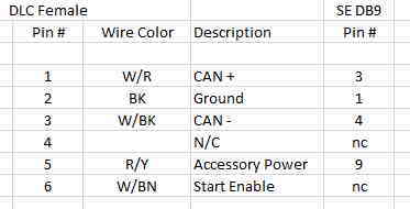
For color codes, the code on the left is the color of the wire and the code on the right is the color of the stripe on the wire. For example, BK-W is a black wire with a white stripe. Table 1: Wire and wire stripe color codes. DB9 24 AWG D-Sub Cables are available at Mouser Electronics. Mouser offers inventory, pricing, & datasheets for DB9 24 AWG D-Sub Cables.
RTS RJ12 Adam Frame <> Key Panel
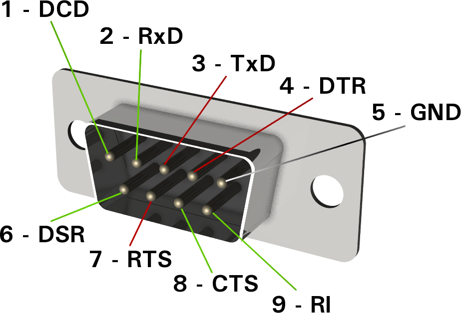
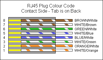
As other reviewers mentioned, the wire colors are not standard. I ordered two of them and the pinouts were the same for both so maybe they're all configured the same way. In case you need it, the pinout from the RJ45 (Colors following T-568B) to DB9 wires is RJ45 to DB9 Wires 1(OW) - Blue wire 2(O) - Orange 3(WG) - Black 4(B) - Red 5(WB )- Green. Wiring/pins via continuity check & color when using blunt cut multi-strand cables. Standard DB9 and DB9M Pin-out The following pin-out chart describes the safest and generally compatible arrangement when connecting a non-Alicat DB9 wire to a DB9 or DB9M equipped Alicat. Not all features may be available between brands, but the common. Conductor color; 1: white: 2: brown: 3: green: 4: yellow: 5: gray: 6: pink: 7: blue: 8: red: 9: black.

- KP's have both RJ12 and DB-9 connectors to connect with the main frame. Either can be used. (no menu selection needed)
- There's no Spec'd color code from RTS, because it depends on the type of wire being used.
- CAT5 is frequently used and this color code is common, based on the USOC Telco standard except Blue/White & Blue is not reversed.
- It's good practice to keep the signals pairs intact on twisted pairs, this helps minimize noise and interference.
- The polarity of Data pair must be maintained, so if using RJ12's crimp the same way at each end.
- Since a KP has both the RJ12 and 9 Pin wired in parallel together - the orange pair can be used as a way of snooping on the audio going to that panel (from the frame) this is useful if the KP's wiring doesn't go through a patch bay.
- Most integrators use audio cable (not Cat5) for 9 pins, the color code below is for reference.
RTS RJ12 Adam Frame <> Key Panel
The mix of DB9, RJ-12, and RJ-45 inevitably means adapters, these modular versions are very common, I prefer the Star-Tech brand since their color code is consistent and follows standard telco wiring
(If you use any other adapters you must confirm the wiring scheme first, different brands use different color codes)
The following drawings are all for Star-Tech!
Db9 Serial Cable Wire Colors

The color code is;
- Blue
- Orange
- Black
- Red
- Green
- Yellow
- Brown
- White
- (NC)
RTS RJ12 Adam Frame <> Key Panel
To use normal Cat 5 cable (568B) for intercom.

USES
- RVON IO to KP
- Extending existing 9 pins, (out of a truck) to an external panel
Db9 Wire Color Code

NOTES
- KP panel needs a male 9 pin and frame side a female 9 Pin
- The pins are all straight 1>1, 2>2 through 8>8
- The intercom signals end up on the following pairs
Orange (data) Blue (from matrix) Brown (to matrix)
Green / Green White are not used.
Photo 4 (far right) shows a short custom RJ12 to RJ45 adapter barreled into a standard Cat5 cable (this would also have one of the 9 pin adapters (above) at the KP end too)
Db9 Color Code Pinout
Having a few of these adapters is a quick way to deploy external KP's, compared to finding raw CAT 5 cable, tools, connectors and crimping RJ12's at each end.
RTS RJ12 Adam Frame <> Key Panel
Below Left (BLUE)
RVON IO 9 Pin to RJ12 - to use Flat Wire / (Silver Satin) to a KP
Below Right (PINK)
RVON IO 9 Pin to RJ12 Crossover to go directly into an Adam Frame via XCP. (this would be instead of using an RVON card in the frame)
9 Pin Serial Cable Pinout
NOTE: the breakout of an RVON is wired the same as the frame side (not the KP side) so the IO audio OP has to flip to the frame IP and Frame OP to the IO audio IP - hence the crossover wiring.
